Application Manual 1.4a
0.- Install.
1.- Enquiry Menu.
1.0.- General Options.1.1.- Total sum of length and perimeter.
1.2.- Total sum of projected length.
1.3.- Total sum of area.
1.4.- Total and partial sum of length for user defined paths.
1.5.- Radial distance.
2.- Export Menu.
2.0.- General Options.2.1.- Exportation to Excel of Length and/or Area by selection.
2.2.- Exportation to Excel of projected Length by selection.
2.3.- Exportation to Excel of coordinates from vertexs, centers or points.
2.4.- Exportation to Excel of vertexs coordinates by condition.
3.- Import Menu.
3.0.- General Options.3.1.- Importation of sets of points in AutoCAD from a Excel sheet.
3.2.- Importation of polylines series in AutoCAD reading the two coordinates of each vertex from a Excel sheet.
3.3.- Importation of 3D-Polylines series in AutoCAD reading the three coordinates of each vertex from a Excel sheet.
3.4.- Importation of texts reading the coordinates of their insertion point from a Excel sheet.
4.- Transform Menu.
4.0.- General Options.4.1.- Transformation to points.
4.2.- Transformation to 3D-polyline.
6.- Survey Menu.
6.0.- Terrain Section.6.1.- Basic Triangulation.
6.2.- Mesh from a set of objects.
6.3.- Volume from a Triangulate Mesh.
7.- Counters Menu.
7.0.- General Options.7.1.- Texts.
7.2.- Blocks.
8.- Measurements Manager.
8.0.- Overview.8.1.- File Menu.
8.2.- Tree Menu.
8.3.- DataGrid.
8.4.- Help Menu.
8.5.- Additional Information.
9.- CAD Library Manager.
9.0.- Overview.9.1.- File Menu.
9.2.- Tree Menu.
9.3.- DataGrid.
10.- Various Menu.
10.0.- Scale object by area reference.10.1.- Block multiple insert.
10.2.- Graph a set of points.
10.3.- Insert Crosses.
10.4.- Copy to layer.
10.5.- Copy to drawings.
10.6.- All visible.
10.7.- Discard duplicate points.
0.- Install.
InnerSoft CAD has a launcher that add a drop-down menu and toolbar to AutoCAD menu collection. Anyway, you must set 'Classic View' in AutoCAD 2009 and AutoCAD 2010 to access InnerSoft CAD Menu.InnerSoft CAD needs the following packages installed on your computer: Microsoft Net Framework 2.0, Visual Basic 6 SP6 Runtime Library and Microsoft Windows Script 5.6.
If some previous version of InnerSoft CAD (demo or full) is already installed on your computer, you must uninstall it and remove the folder 'C:\Program Files\InnerSoft\' before installing a full version.
User must be Logged into the system as Administrator (NT-based versions of Windows) to install successfully InnerSoft CAD.
This application will not work properly if is not installed in its default folder: 'C:\Program Files\InnerSoft\'.
You CAN'T run a version of InnerSoft CAD in a not relative AutoCAD version. InnerSoft CAD for AutoCAD 2010 will not work on AutoCAD 2009, and so.
1.- Enquiry Menu.
1.0.- General Options:
The selection of AutoCAD objects works in three ways or Selection Modes:- Select All: it will add all the objects appearing in the drawing to the selection to be dealt.
- Select on screen: it will allow you to select individually or by picking the objects that you want to deal.
- Select by layers: that deal with all the objects appearing in the layers selected. In order to select a layer you must select any object contained in it.
You can also choose the set of decimals which will be used to show or export the measures, being the range from 0 to 8 decimals.
There are checkboxes in menus to perform filters of objects depending on the type of objects. That is to say, if we foresee that arcs are to be included in our selection but we do not want to add their length to the total sum, then we should only deactivate the box "Arch".
Insert Text. Available for tabs 'Lengths', 'Projected Lengths' and 'Areas'. If checked, text will be placed near the object showing its property value. In tab 'Areas' a checkbox allows to insert a text showing object perimeter. You can choose a measure unit from 'Unit' list. Checking option 'Center/Start', text will be inserted at start point of línes, polylines, etc, or center of arcs, circles or ellipses. Checking option 'Center Box', text will be inserted at center of circunscribed object box.
1.1.- Total sum of length and perimeter.
TIP: Multiple lines have not the property of length, but this can be calculated with the coordinates of their vertex as app do.
 Working with following entities:
- Lines
- 2D-Polylines
- LW-Polylines
- 3D-Polylines
- SP-Lines
- Arcs
- Ellipses
- Circles
- MLines (computed length)
- Regions
1.2.- Total sum of projected length (on plane XY).
Working with following entities:- Lines
- 3D-Polylines
1.3.- Total sum of area.
Working with following entities:- 2D-Polylines
- LW-Polylines
- 3D-Polylines
- SP-Lines
- Arcs
- Ellipses
- Circles
- Regions
- Hatchs
TIP: It does not care if polylines are open or closed whenever we want to calculate their area. That polyline which is not closed will have the same area as that it would have if an additional line linked their initial and final extremes.
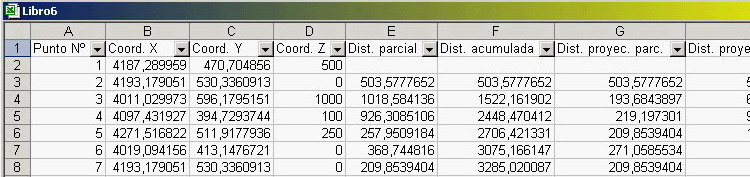
1.4.- Total and partial sum of length for user defined paths.
It includes option of exportation of values to Excel either for real distances or those projected on an XY plane- Consecutive: with no leaps between them.
- No consecutive: there can be leaps between them
Export values, to Excel of the coordinates of the selected points, the partial distance between them and the total one, either real or projected.
Insert index in AutoCAD, which will be done in a layer with the name of "0-IS-Index", which will appear turned off by default, hence it will have to be turned on to check such indexs. Besides, this layer will be completely cleaned before every performance of the application. In order not create confusion between the indexs of an operation or the other. The usefulness of the indexs lies in the ability of easily correlating the dates exported to Excel and the objects of AutoCAD from which they come, apart from marking the points which have been used.
1.5.- Radial distance.
Determines the real distance and that projected from different points which are being chosen in the screen according to the centre also selected in the screenOptions are:
- Export values to Excel, from the coordinates of the selected points apart from the real and projected length and the difference of rates.
- Include angles, between the centre and the points selected in the values that will be exported to Excel
- Insert Index, in AutoCAD.
2.- Export Menu.
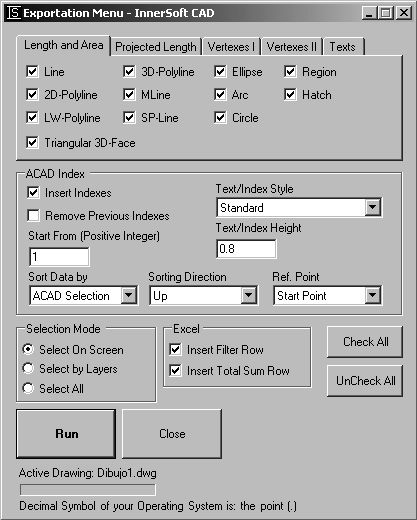
2.0.- General Options.
The selection mode works as in Enquiry Menu, as well as the filters by type and numbers of decimals positions. Besides we have 3 check-boxes to:Insert Filter Row, in the sheet of Excel. The row of filters allows to make discriminatory selections depending on the different values wich are presented in each column. That is to say, if we have five different layers in the column, choosing the name of any layer from the filters combo-box, we will see the rows of values for only the elements in that layer.
Show Resume, wich will show a summary of objects and exported values.
Insert Total Sum Row, in the sheet of Excel. The row of sum will appear at the end of values in columns for area or length or projected length, this way showing the sum of values of the whole column.
ACAD Index. Containing the following options:
- Insert Index, in AutoCAD
- Remove Previous Index, if other indexs had been already inserted in the same drawing.
- Index Height, to introduce the height of the AutoCAD text used to represent the index.
- Index Text Style, to choose the style of the AutoCAD text used to represent the index.
2.1.- Exportation to Excel of Length and/or Area by selection.
 Working with following entities:
- Lines
- 2D-Polylines
- LW-Polylines
- 3D-Polylines
- MLines (computed length)
- SP-Lines
- Arcs
- Ellipses
- Circles
- Regions
- Hatchs
2.2.- Exportation to Excel of projected Length by selection.
Working with following entities:- Lines
- 3D-Polylines
TIP: The limit for these 3 functions (2.1, 2.2 y 2.3) is 65.536 objects (the maximum that a sheet of Excel allows). If you need to export the data of more objects, this must be done in different parts.
2.3.- Exportation to Excel of coordinates from vertexs, centers or points.
Working with following entities vertex:- Points
- Lines
- 2D-Polylines
- LW-Polylines
- 3D-Polylines
- MLines
- SP-Lines
- Arc Centers
- Ellipse Centers
- Circle Centers
- 3DFaces
- 2D Solids
- Polyface Meshes
- Polygon Meshes
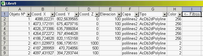
TIP: The only thing exported from arcs, ellipses and Circles is the coordinate of their centers.
TIP: As Excel does not allow sheets with more than 65.536 cells, the application will divide the list to be exported in sheets of approximately 50.000 rows each one, creating new sheets as they are needed. Moreover, the book of Excel will be saved before beginning to fill the second sheet and it will be saved whenever a new sheet will be filled.
2.4.- Exportation to Excel of vertexs coordinates by condition.
 For any of the following conditions:
- Points are not at greater real distance from a center than a introduced value.
- Points are not at greater projected distance than a introduced value.
- Points are not out of an intervals of introduced elevations.
Angle Included, which will insert in a Excel column (for the two first options) the angle formed with the horizontal plane by the line whose vertex are the center of selection and the point wich fulfills the condition.
Transform Vertex To Point, that will draw the vertexs that fulfills the specified condition.
Coord. Z as Elevation. This option will also be used in other menus. The 2D-Polylines always have 0 as Z coordinate (independently of their elevation), while the common polylines (LW-Polylines) does not have a specified Z coordinate, only elevation (only 3D-Polylines have Z coordinated non by default). Not withstanding, such polylines are sometimes provided with an elevation to specify their height position in space. This option has to be activated in order to consider that elevation as the Z coordinate of the vertexs of the polyline.
3.- Import Menu.
3.0.- General Options.
Decimal Symbol: The options of Import Menu only work with the format with a suitable number. That is, numbers which use the same decimal symbol that user have chosen in the configuration of his Operative System, not being significant if they use or not the hundreds symbol separator (obviously, this symbol will not be the same as decimal symbol in order to avoid any kind of confusion). If this requirement is not fulfilled, the execution of the application will fail. You can configure the numbers format properly from the format options of the Excel cells. You can also change the decimal symbol in the configuration of your Operative System, but then you will have to restart Excel as well as AutoCAD so that changes are effective. If you want to know the decimal symbol that your OS is using, then must go to Start > Settings > Control Panels > Regional and Language options > Customize > Decimal symbolMessages (Index). In Index Method, marking this checkbox the app will send you a message if it does not find enough data while creating a poyline from Excel values list (less than two values).
Polylines can be drawn in:
- A new Drawing, that will be added to AutoCAD where Polylines will be drawn.
- A new Layer, that will be added to active drawing, The layer name will be "0-IS-Import" .
- Active Layer, that is, Polylines will be drawn in the current active layer.
In none of the cases, the application will accept completely empty rows of Excel before the start of data. If such row exits the process will be aborted.
In all the cases, the sheet of Excel read is the active sheet. User must not activate a different sheet while the application is reading data from the working sheet.
3.1.- Importation of sets of points in AutoCAD from a Excel sheet.
Using its three coordinates read from a Excel sheet. The three first columns of Excel are checked from the first row to the last numerical value written in the first column. If application find a blank cells in these three columns, its value will be considered zero. Empty triads in a row before the end will set a point on AutoCAD origin. There must not be any text in the first three columns.3.2.- Importation of polylines series in AutoCAD reading the two coordinates of each vertex from a Excel sheet.
 From
a Excel sheet, by three methods:
From
a Excel sheet, by three methods:
Simple Method:
Only one polyline is imported taking the data from the first row of Excel containing coordinates to the last one containing numerical values. If there is any blank cells in the first or second column, the value will be considered as zero. There must not be texts in any of the two columns. There must not be completely empty rows among the list of data (preventing this way inserting polyline vertexs in the origin); application will send a message warning about these circumstances.Space Method:
Series of polylines will be imported. The two first columns of the Excel sheet are checked. It there are at least two consecutive numerical values in the first column, the application will start a polyline, taking data until it find a blank cell or a text in this column. There must not be texts in the second column in a data serie for a polyline. If there is any blank cells in the second column, the value will be considered as zero.Index Method:
Series of polylines will be imported. The two first columns of the Excel sheet are checked. The first column must have an index (natural numerical value) to express the individuality of every polyline (it does not represent an order of indexs) Every time the index change, the application will finish a polyline and will start a new one. If there is any space in the first or second column, the value will be considered as zero. If there are blank cells in the indexs column, the application will consider that there is no change of index, so you can insert the indexs only at the beginning of the first triad of values of every polyline.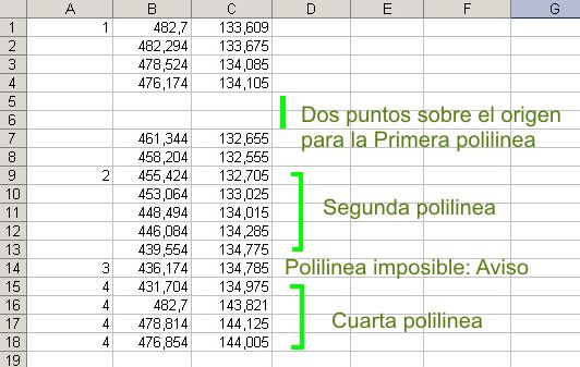
TIP: If you are going to use an application exported sheet to import polylines, must remove the row of filters and maybe, depending on the method, the row of indexs.
3.3.- Importation of 3D-Polylines series in AutoCAD reading the three coordinates of each vertex from a Excel sheet.
From a Excel sheet, by three methods:Simple Method:
Only one 3D-Polyline is imported taking the data from the first row of Excel containing coordinates to the last one containing numerical values. If there is any blank cells in the first, second or third column, the value will be considered as zero. There must not be texts in any of the three columns. There must not be completely empty rows among the list of data (preventing this way inserting polyline vertexs in the origin); application will send a message warning about these circumstances.Space Method:
Series of 3D-Polylines will be imported. The three first columns of the Excel sheet are checked. It there are at least two consecutive numerical values in the first column, the application will start a polyline, taking data until it find a blank cell or a text in this column. There must not be texts in the second or third column in a data serie for a polyline. If there is any blank cells in the second or third column, the value will be considered as zero.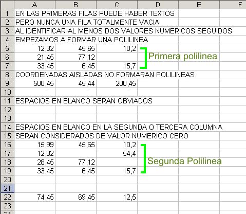
Index Method:
Series of 3D-Polylines will be imported. The three first columns of the Excel sheet are checked. The first column must have an index (natural numerical value) to express the individuality of every polyline (it does not represent an order of indexs) Every time the index change, the application will finish a polyline and will start a new one. If there is any blank cell in the three first columns, the value will be considered as zero. If there are blank cells in the indexs column, the application will consider that there is no change of index, so you can insert the indexs only at the beginning of the first triad of values of every polyline.3.4.- Importation of texts reading the coordinates of their insertion point from a Excel sheet.
Application will read the three first columns of a Excel sheet to get the insertion point coordinates of every text groups. If there is any blank cells in the three first columns, the value will be considered as zero, so if texts have no Z coordinate different to zero you can use a blank third column. There must not be texts in the three first column, except if you have checked Define Field by First Excel Row option; in this case, whatever exists in the first row of the first three columns will be neglected. If any of the fields are the insertion coordinates, the first three columns must be duplicated. The values for texts must be written in the columns from the third one. Completely empty rows of data are allowed, but they will prompt blocks over the origin with no texts.General Submenu:
Number of Text Excel Columns: Number of columns (not taking into account the first three ones) which contain texts. The texts will be inserted vertically disposed in rows from the insertion point.Text Row Spacing: Vertical separation between rows that form every group of texts.
Vertical Displacement from Insertion Point: Vertical separation from the insertion point of the top-left corner of first text.
Horizontal Displacement from Insertion Point: Horizontal separation from the insertion point of the top-left corner of first text.
Text Height: Height of the texts inserted in AutoCAD.
Blocks of block attributes Submenu:
Insert All Independently: Insertion point and every single text will appear in AutoCAD as independent entities.Insert Text as Block (Independently of Point): Every group of texts is inserted as a block. A singular point is added in the block insertion point, but it does not belong to the block.
Insert Text and Point as Block: Both the point and the group of texts belong to a block.
Insert Text and Point as Block Attribute: Texts belong to a block, where every text is an attribute of the block (attribute fields are getting manually from a input box or from the first row of the text columns).
Block Fields Submenú:
"Field" must appear in the first row of Excel columns that contain texts.Insert Text without Field: Only texts found in every cell of the column is inserted.
Define Fields Manually: Application will show as many input boxes as columns of texts, and user must input manually the field of every column.
Define Field by First Excel Row: In the first row of the Excel columns that contain texts must be written the field.
If there are columns that don't need fields, the cell can be blank.
NOTA: Hay una gran diferencia entre el concepto de Campo para un Bloque y para un Atributo de bloque. En el primer caso, el campo aparecerá precediendo al valor de cada texto insertado, formándose una única cadena de texto a insertar con el campo de la columna y el valor correspondiente de cada celda, mientras que en el segundo caso el campo corresponde al identificador del atributo de bloque, y no aparecerá en los textos insertados.
Para grandes cantidades de textos a importar se recomienda usar la opción de Atributos de Bloque, pues al crear un ÚNICO bloque del cual se modifica su punto de inserción y valor con los textos de cada fila el proceso resulta mucho mas rápido. Si se insertan los textos como bloque entonces se ha de crear un bloque diferente para cada grupo de textos, y esto recarga el dibujo y ralentiza el proceso de importación. Además, los atributos de bloque pueden ser exportados desde AutoCAD a diferentes formatos de tabla (*.xls, *.csv, *.txt y *.mdb) desde 'Herramientas/Extracción de Atributos'.
4.- Transform Menu.
4.0.- General Options.
Options are:- Show Resume, send a window message at the end of operations dispalying number and type of objects transformed.
- Coord. Z as Elevation, set as Z coordinates of points the elevation value of Polyline and LW-Polyline.
- Remove Originals, erase objects transformed.
- A New Drawing
- A New Layer
- Active Layer
4.1.- Transformation to points.
Working with following entities:- Lines
- 2D-Polylines
- LW-Polylines
- 3D-Polylines
- MLines
- SP-Lines
- Arcs Centers
- Ellipse Centers
- Circle Centers
- 3DFaces
- 2D Solids
- Polyface Meshes
- Polygon Meshes
4.2.- Transformation to 3D-polyline.
Working with following entities:- Lines
- 2D-Polylines
- LW-Polylines
- MLines
- SP-Lines
- 3DFaces
- 2D Solids
- Polyface Meshes
- Polygon Meshes
NOTA: 3DPolyline transformed from a closed polyline will not appear closed.
6.- Survey Menu.
6.0.- Terrain profile.
Still not translated.6.1.- Basic Triangulation.
This command uses Delaunay Triangulation Method over a cloud of points. User must choose if triangulation includes the drawing of 3D-Faces, lines or both (drawing resulting lines take more time than drawing resulting 3D-Faces). During execution, cloud of points will be checked to reject duplicated points: those that have same X and Y coordinate. Application will not control circumscribed radium of triangles.6.2.- Mesh from a set of objects.
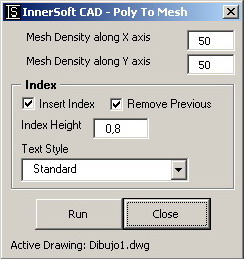 This
command create a polygonal mesh from vertexs of following objects:
polylines, LW-Polylines, 3D-Polylines and lines. User must input mesh
density of axis X and axis Y (a number between 2 and 256). Application
will ask for a objects selection, lower right corner and upper left corner
of mesh. Then it will create terrain sections from vertical sections
defined by every axis (vertical and horizontal axis inside the corners).
Vertex coordinates of mesh are created following two criteria:
This
command create a polygonal mesh from vertexs of following objects:
polylines, LW-Polylines, 3D-Polylines and lines. User must input mesh
density of axis X and axis Y (a number between 2 and 256). Application
will ask for a objects selection, lower right corner and upper left corner
of mesh. Then it will create terrain sections from vertical sections
defined by every axis (vertical and horizontal axis inside the corners).
Vertex coordinates of mesh are created following two criteria:Section criteria: Mesh vertexs that belong to terrain sections will take height by interpolation. If they have a height from a X axis section and also a height from a Y axis section, it is used the arithmetic mean from that two values.
Minimum distance criteria: Those mesh vertexs outside terrain sections may take its elevation from the floor of mesh (lowest point of mesh) or may take its elevation from the nearest point.
Mesh axis which do not have intersection with any object will give vertex on the mesh floor. It is recommended that mesh limits fall completely over the set of objects. User must check how application works in different cases, testing different mesh limits.
TIP: You should not explode polylines into lines, because application work fastest with polylines.
6.3.- Volume from a Triangulate Mesh.
Three different methods to compute the volume from a triangulated 3DFace mesh. Volume is referenced to a z plane located in lower vertexs of all 3DFaces vertexs.7.- Counters Menu.
7.0.- General Options.
Common options for selection mode and index inserting.7.1.- Texts.
Application will compare texts in order to find. First, it will ask for the objects where user want to make the search. It will only allow Texts and MTexts. Then, it will ask for the pattern (only one Text or MText). Application will get the string of that object and will search any coincidence over initial selection. Options:- Case Sensitive: Text sometimes exhibits case sensitivity, that is, words can differ in meaning based on the differing use of uppercase and lowercase letters. If you check this option, a string like "PoP" will NOT be equal to a string like "pOp".
- Exact Match: If you check this option, application will search for the exact string of characters that you type in. Otherwise, application will search strings that match pattern as a substring. So if you type in "Mob" it will match a string like "Mobile one".
7.2.- Blocks.
Options:By Name:
Application will ask for a set of AutoCAD blocks. Then it will ask for a AutoCAD block (only one block; it is the pattern). Finally, it will identify all blocks that belong to selection and match the pattern.Insert and Count All blocks in Drawing:
Application will identify all defined blocks. It will ask for a point where user wants all defined blocks draw and listed. Near every blocks, will appear its name and number of insertions (excluding listed insertions).8.- Measurements Manager
8.0.- Overview.
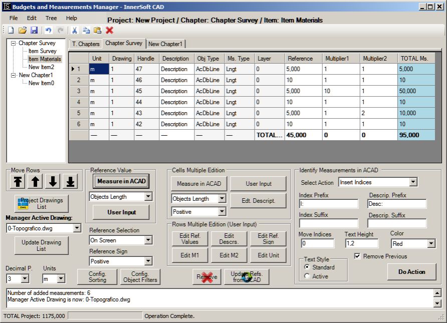
Measurements Manager consists of a tree on the left, which list and organized the chapters and items of each chapter. At center is the table, which lists measurements of each item, computing total sum of different columns. Measurements are length or area values get from AutoCAD objects. In the lower part of the interface is the status bar. Its function is purely informative and does not serve to make entries or to execute commands.8.1.- File Menu.
Menu Items are:- Open Project. Open a text file in which previously has been saved a set of measurements performed with Manager.
- Save Project As... Save in a *.txt file all data in the Grid. You can open this file lately and work again with all this data.
- Export Project. Export All data to a MS Excel sheet. Options are:
- Export Chapters and Items. Export to a MS Excel sheet all data in Grid.
- Export Chapters. Export to a MS Excel sheet all chapters data in Grid.
- Exit. Close Application.
8.2.- Tree Menu.
On the basis of a double-click mouse selection criteria, nodes can have different states: Active Node and Selected Node. Active Node (double-click) shows its data on the grid. Selected Node (single-click) allows operations such a Remove Chapter, Remove Item, Edit Name, Add Item...Menu Items for selected nodes are:
- Remove Chapter. Deletes a chapter, its items and corresponding measurements.
- Add Chapter. Add a new chapter, becoming this one both the Active Node and Selected Node.
- New Item. Add a new item to a chapter. DataGrid will display a empty table. To add an item user must select a chapter node or any of its items.
- Remove Item. Remove an Item and all its measurements. To remove an item it must be selected from Tree.
- Edit Name. Change item or chapter name at user input. Item or chapter node must be selected. Does not allow blank names or special characters shuch a pipe: |
- Expand All. Expand All nodes in the tree.
- Collapse All. Collapse All nodes in the tree.
8.3.- DataGrid.
DataGrid has two display modes.Chapter Columns.
At double-click on a chapter node in the tree, Manager will display on table all chpater items. Columns are:- Index. Displays a cumulative index based on the position for each item in the tree.
- Name. Displays the name for each item in the chapter.
- Description. Displays a description for each item in the chapter.
- Nº Measurements. Displays number of measurements for each item in the chapter.
- Total of Reference. Displays the total sum of all values for the reference column for each item in the chapter.
- Total. Displays the total sum of all values for the total column for each item in the chapter.
Item Columns.
Mesurements list will be displayed at table on double-click over a selected Item from tree. Columns are:- Index. Shows a cumulative position index for each measurements in the item.
- Id ACAD. It is the unique identifier set by AutoCAD for each object in drawing. Its utility is to identify measurements insert indexs, etc..
- Description. The description of each measurement in item.
- Type. AutoCAD entity type of the object from which measurement in reference column comes.
- Layer. Layer of the object from which measurement in reference column comes.
- Reference. Column that list reference measurements: lengths or areas of a set of selected objects from AutoCAD drawing.
- Multiplier1. A column for a numeric values that multiply reference measurement values.
- Multiplier2. Second multiplier for reference measurement values.
- Total. Total value from multiplication of reference measurement values and both multiplier columns.
Referent Column.
Referent Column list length or area of a set of AutoCAD objects. Can also display a distance from two points in AutoCAD screen, or a user input. These two entry types have a special mark ("DIST." or "USER."), cos they are not associated to any AutoCAD object. If user edit the reference value get from a AutoCAD object, then measurement will show mark "USER.", and will be dissociated from the original AutoCAD object. Edition can be made by "Common Value" or "Single Value" (see section 'Selection and Edit'). User can choose from three different selection methods to make AutoCAD objects selection. Can also filter your selection pressing 'Configure Object Filter' button.
Referent Column only accept measurements from ONLY ONE drawing. If you need to work with measurements from another drawing, must add a new item.
Multipliers Columns.
Once we have a list of measurements in the reference column, can insert values into two columns to obtain a multiplier total in the last column of the table (column totals). To insert these values in the column user must perform a selection of rows, either multiple selection or single selection, and then press button 'Set Value'. The value types are:
- Object Area: Area from ONLY ONE object selected from AutoCAD active drawing screen.
- Object Length: Length from ONLY ONE object selected from AutoCAD active drawing screen.
- Distance: Distance from AutoCAD active drawing screen.
Edition can be made by "Common Value" or "Single Value" (see section 'Selection and Edit').
Both multiplier columns may get values of any of the opened AutoCAD drawings, so have not the restriction on the reference column. Just activate any drawing where you want to measure and then press button "Set Value".
Minor Options.
Selection And Edition.
User must click on the grayish header row at table left to select a row. Can perform multiple selections with 'Cntrl' or 'Shift' keys.When editing the description of a multiple selection of items or measurements, user can choose from two modes which appear in the 'Multiple Edition' box):
- Common Value: Input A Common Value for a multiple row selection.
- Single Value: Input A single Value for every row in selection.
Identify Measurements in AutoCAD.
'Identify Meas. in ACAD' button shows on AutoCAD screen the object associated to a single measurement on grid. User can also insert a text near every object of AutoCAD showing its index or despcription getting from the grid.Manager Active Drawing.
It is the drawing used by Manager for object measurement. If there are some drawings opened in AutoCAD, Manager will work with its Active Drawing.If Manager Active Drawing is closed, application will get the first one in AutoCAD opened drawing collection.
If user changed Referent Drawing from path, can press 'Reassociate Drawing to Item' button. A dialog box will ask for the new path for drawing.
If user reassociate a item to a different drawing from wich made first measurements, 'Insert Indexs' or 'Insert Description' fail to identify the objects which index or description were inserted.
So, Manager distinguish:
- AutoCAD Active Drawing is active drawing of AutoCAD.
- Manager Active Drawing is active drawing of Manager. Manager operations will apply over this drawing.
- Item Associated Drawing is AutoCAD activated drawing from wich user added the first measurements to this item. Each item reference column is associated with a single drawing (with a path in the computer). Columns of multipliers do not follow this condition.
Decimal Places.
A drop-down list will let user to choose number of decimal places for both the numerical display in the table and export measurements to Excel. App operates with raw values, 12 decimal places, so there will be no problem when moving from a smaller number of decimal places to a larger one. It's just a matter of visualization, not storage or calculation.Decimal Separator.
The decimal separator or decimal point or decimal comma is a symbol used to mark the boundary between the integral and the fractional parts of a decimal number in a positional numeral system. It depends on your Regional Configuration. Manager will shows your current Separator.8.4.- Help Menu.
Menu Items are:- Help. Open this PDF.
- Credits. Shows InnerSoft email and webpage.
- InnerSoft Web. Open InnerSoft webpage.
8.5.- Additional Information.
Objects and Properties.
Treatment of AutoCAD properties is:- Lines: Length
- 2D-Polylines: Length and Area.
- LW-Polylines: Length and Area.
- 3D-Polylines: Length.
- M Lines: Length computed from its vertexs.
- SP-Lines: Area
- Arcs: Area and length as arc perimeter.
- Ellipses: Area.
- Circles: Area and length as object perimeter.
- Regions: Area and length as object perimeter.
9.- CAD Library Manager.

9.0.- Overview.
CAD Library Manager consists of a tree on the left which lists books and drawings for each library, and a table at center which shows drawings of each book. User can create, open or save different libraries, which contain a series of AutoCAD drawings (*.dxf or *.dwg) organized by books.The basic function of the Manager is to have access to lot of drawings that are usually spread over different folders on your computer (in order to open or to insert any of them in AutoCAD). User have a series of controls to add the drawings, either automated or manually, to the books in each library that creates.
9.1.- File Menu.
Menu Items are:- New Library. Creates an empty library with a empty book.
- Open Library. Open a text file which previously user saved a library of CAD drawings from Manager.
- Edit Library Name. Edit the name of the active library. Names can not be empty strings or contain the following symbol: |
- Save Library. Save in your computer all data of Active Library in a *.txt file. You can open this file lately and work with all data again.
- Close Library. Close active Library.
- Exit. Close application.
9.2.- Tree Menu.
Application distinguish two node states: Active Node and Selected Node . Active Node list its elements in the table. Selected Node will not display its element, but allows operations as "Delete Book" "Edit Book Name" and others.So, a book will be activated at double click, displaying all its elements on the table. To select a node only need make a single click on it.
Menu Items are:
- New Book. Add a new book. Table will displays blank rows for this book.
- Remove Book. Remove the book and all its drawings.
- Edit Book Name. Open a text to change the name of book. The node of that book or one of his drawings must be selected. Names can not be empty strings or contain symbol: |
- Expand All. Expand all nodes in the Tree.
- Collapse All. Collapse All nodes in the tree.
9.3.- DataGrid.
The table displays drawing list of active node selected from tree.Columns.
Table datagrid displays drawing list of each book by double-clicking on the corresponding book in the tree. App distinguish the following columns in the table:- Index. Displays a cumulative index based on the position of drawings for each chapter in the tree.
- Name. Name of every drawing in table.
- Description. This description is editable from "Edit Description" button. Edition can be made by modes 'Common value' or 'Single Value'.
- Path. The path of the drawing in your computer.
Add or remove entries in a Book.
- Add Drawings. Drawings are added to the table from a dialog box whereby the user can select their CAD files from computer folders. Selection can be multiple.
- Add Folder Drawings. Search and add all drawings in a folder. User can choose from *.dwg files or *.dxf files or both. You can also choose whether add all drawings in a root folder or drawings that also exist within the subfolders in root folder. This is the option 'Include Subfolders'.
- Remove Drawings. Drawings will be removed from the table selecting them and then pressing 'Delete Drawings' button. User must click on the grayish header row at table left to select a row. Can perform multiple selections with 'Cntrl' or 'Shift' keys.
Insert or Open Drawings.
User can choose items from the table and insert them as blocks in the active drawing. Just press button 'Insert Drawing as Block'. Can also choose at which point of the active drawing blocks will be inserted. Can do it pressing button "Select on Screen".To open drawings in AutoCAD, user must select them from the table and press button 'Open drawing'. If a drawing was yet open at that AutoCAD session, it will not be opened again.
Check and change of paths.
Some controls allows to verify that each drawing paths in table match actual location in the computer. To verify that paths are correct user has the buttons:- Check Drawing Paths. Check path of drawings selected in table.
- Check Book Paths. Check path of all drawings in active book.
- Check Library Paths. Check path of all drawings in active library.
Drawing Preview. Displays the preview of a selected drawing. May Not if:
Drawing is prior to AutoCAD 14
Drawing was saved with no previsualization
Protect Book from Repetitions. This option applies individually on each book. Its function is to prevent the addition to the book of drawings that already have. Two drawings are considered equal if have the same name and same path. This option is marked by default, and if the user wants to add repeated drawings must uncheck it. If a book that had that option unchecked is lately checked, then the program will remove all repeated drawings in the book.
Active Drawing. Drawing on which you can insert any other drawing listed on table.
Edit Drawing Description. the description of the drawings selected in the table. User can use the 'Common Value' or 'Single value'. Names can not be empty strings or contain symbol: |
10.- Various Menu.
10.0.- Scale object by area reference.
You can select any of this objects (only one object): LWPolyline, Circle, Region, Ellipse, Arc, Polyline and/or Spline. Then a window will show you the area of this object. In this window, you must input the numeric value of the new area for this object. Once the object is scaled, the program will send to the command line the scale factor used in the operation10.1.- Block multiple insert.
The program first will ask for a block insertion on the drawing screen. Then, in a second selection, you can select any of this objects (one object or a set of them): Point, Line, Polyline, LWPolyline, 3DPolyline, Spline, Mline, 3DFace, Solid 2D, PolygonMesh, PolyfaceMesh, Arc, Circle and EllipseThe block you selected will be inserted in:
- Points
- The vertexs of Line, Polyline, LWPolyline, 3DPolyline, Spline, Mline, 3DFace, Solid 2D, PolygonMesh and PolyfaceMesh
- The centers of Arc, Circle and Ellipse
10.2.- Graph a set of points.
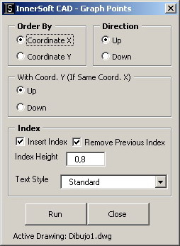 From a windows menu, you must choose:
- If points are ordered by X or Y coordinate. If points are ordered by incrementing or decrementing value (Up or Down/Right or Left).
- If points with identical ordering coordinate must be reordering up or down for secondary coordinate value.
10.3.- Insert Crosses.
You can insert a grid of crosses defined by X and Y interval. Intervals must be positive integer values. Also can choose if insert a text with the (X,Y) coordinates value for every cross.10.4.- Copy to layer.
A window with a combo box will allows you to select one of the existing drawing layers. Then you must select a set of objects on the drawing screen. All the objects will be COPIED to the selected layer. It works in paper or model space.10.5.- Copy to drawings.
You can copy a set of objects to the rest of opening drawings. In a window menu, you must select if you will copy the set of objects to the paper or model space. Also can choose if paste the selected objects as a block or not.10.6.- All visible.
This command will set the visible property to true in all objects of the drawing (usually there is no invisible objects in a drawing).10.7.- Discard duplicate points.
You must select a set of points. Points not duplicated (same X and Y coordinates) will be copied to a layer of name: 0-IS-FilteredPoints© Copyright InnerSoft 2004-2010. All rights reserved.